Hardware
At the heart of this project is the circuity that attaches to the Raspberry Pi and hosts the extra elements that make the thermostat work.
The board integrates the following components:
- 24V AC to 5V DC transformer circuit
- Relays for A/C, heat and fan (simple 5-wire)
- Header for the e-paper display (Waveshare 2.9” with partial update)
- Two partial rings of 8 multi-color LEDs, each controlled w/ an LP5024 LED driver chip for high-frequency dimming and color mixing
- BME280 environment sensor, capturing temperature, pressure and humidity
- A CAT24C256 for i2c-based storage (a component I have some ideas for but honestly have no clue for sure what I’ll do with!)
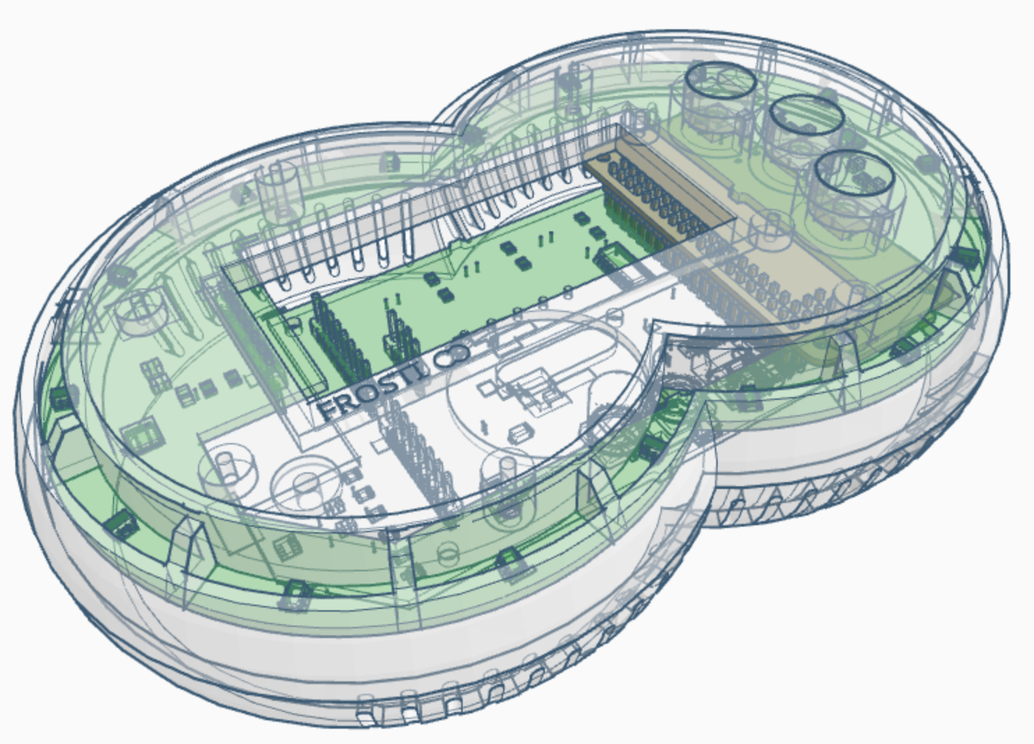
The board is actually two boards, that after being assmebled are detached and installed in different locations.
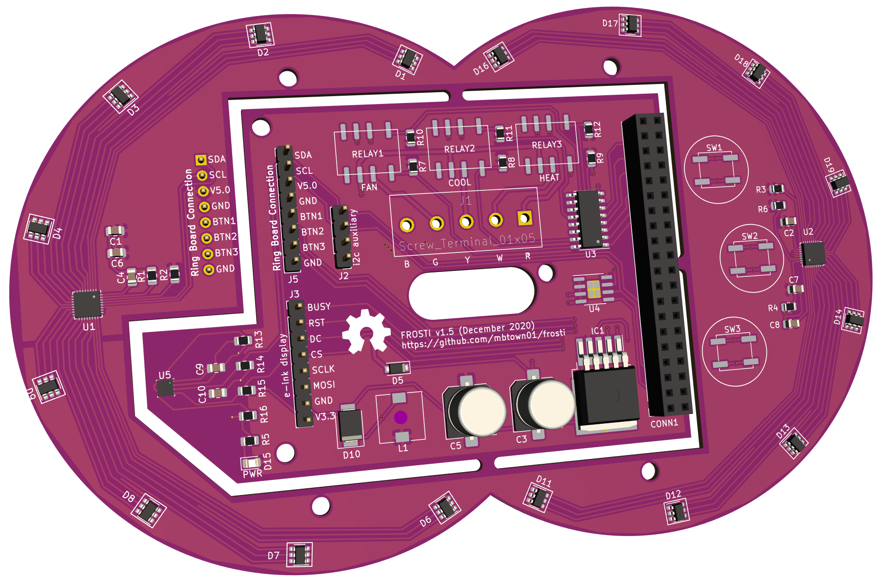
Main Board
Internally there are two PCBs – the main board containing the power conversion circuit, thermostat relays, and the Raspberry Pi header. It also contains the environment sensor, which may need to be relocated depending on the thermals inside the case.
Thermostat connection
FROSTI runs on the standard “5-wire” thermostat configuration, with the following connections:
- Blue – Common ground
- Green – Return to power fan
- Yellow – Return to power A/C
- White – Return to power heat
- Red – Thermostat 24V power input
The main board has a 5-port screw terminal, with the 1st letter of the wire color labeled for installation.
Ring Board
The ring board is a breakout board containing all the LEDs for the UI.
This transparent rendering will give a feel for what the insides look like.
Credits
I’d like to thank Rays Hobby for a great write-up on 24V AC to 5V DC power conversion. I personally run Ray’s OpenSprinkler Pi (OSPi) platform (with the 8-zone extender!) and was inspired to take a shot at my own board by reading his blog posts.