3d Printing and Hardware v1.5 Update
Over the past couple weeks I’ve received my 3d printer and the v1.5 boards from OSHPark and made a bunch of progress. Below is a dump of what went well and what I’ve learned.
3D printing and enclosure design
I have to admit, I had this pre-conceived notion that 3d printing would be easy – just plug it in, feed some filament and go! Once I assembled the printer (the PRUSA Mini+), I spent the next couple days doing test prints to understand the filament I purchased and how it works with the printer. I made one or two plastic blobs in the process, but in general I think I know what I’m doing now.
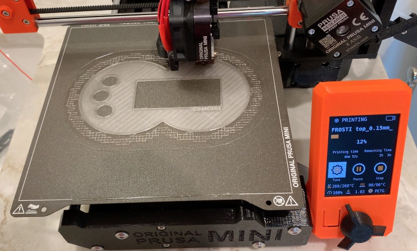
Some thoughts on my first case design…
- Top and bottom fit together nicely, but it’s hard to determine orientation. We need something inside that makes it clear which side is which.
- Need a snap mechanism for the diffuser to attach it to the top
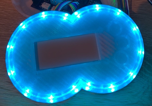
- The diffuser may need significantly more thickness to catch the light, the current design still clearly shows a single LED in each arc segment.
Hardware v1.5 issues
Some things went well, some things… eh, not so much. Here’s the rundown:
SMD soldering seemingly flawless
This is by far my most complicated board I’ve tried to assemble on my own. The LED driver chip pins are very small and close to each other, making it hard to get the solder paste to line up well w/ the stencil. However, after running tests on the board, it seems like every component that went through the reflow process connected perfectly
Pi header orientation 180deg off
Embarrassingly enough, I somehow placed the 20x2 Raspberry Pi header backwards in a way that prevents the Pi Zero from being directly connected. It’s somewhat understandable considering it’s a perfect rectangle of 40 holes that looks the same when rotated 180 degrees. For now, this is okay as it will make a good development setup, but it is quite disappointing that this prototype won’t make it onto the wall…
Hand-soldering GPIO pins creates issues
It would also seem that while hand-soldering the header I somehow got enough solder on one of the relay control GPIOs to flow underneath the header block and bridge one of the adjacent GND pins. For the next board, I’ll need to either be lighter on the solder or find a different technique. My guess is that while getting the solder close to the pin, I actually pushed solder into the hole, creating the issue.
Next steps
For now, I’m going to move forward with this board and focus on updating the user interface to work with the new 3-button layout, the LED light ring, and the e-paper display. This will likely require some kind of web-based simulator so I can run tests w/o any local hardware.